

€450,00
- setting of the Piezoresponse Force Microscopy (PFM) mode,
- optimization of the modulation voltage parameters (frequency, phase and amplitude),
- test measurements in the PFM mode.
Sample description
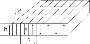
Lithium niobate (LiNbO3) single-crystalline 500-μm-thick plate with roughness less than 10 nm cut normal to the polar axis.
A regular domain structure with period D was created in the sample. The spontaneous polarization has the opposite direction in the neighboring domains. The polarization direction determines the sign of piezoelectric coefficient. Analysis of the local piezoelectric response during application of the modulation voltage allows to reveal the domain pattern.
Specification
|
 |
Quick Start Guide
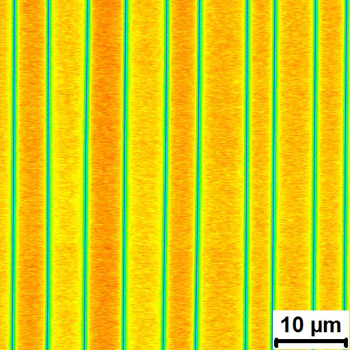
The sample is fixed on the SPM holder and its bottom electrode is grounded. The measurements are held in contact mode. AC voltage with a frequency fmod is applied to SPM tip. The sample surface oscillates with the same frequency. This response is analyzed using the lock-in amplifier. The domain walls contrast can be obtained in the amplitude of the piezoresponse signal, and domain contrast – in the phase of the signal. The typical images obtained by PFM mode are shown in Figure 1.
| a) | b) | c) |
 |
|
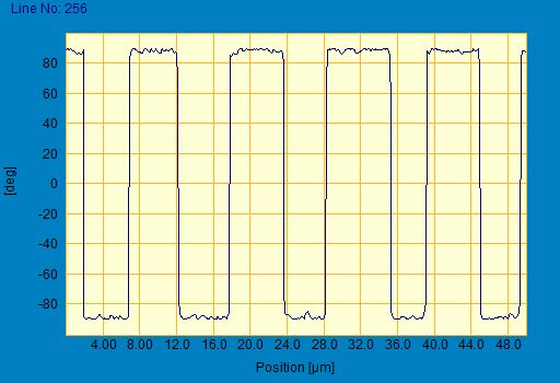 |
Figure 1. The typical domain pattern obtained in the sample by PFM mode:
(a) amplitude
(b) phase of piezoresponse signal
(c) phase profile.
Image obtained by diamond coated conductive tip DCP10.
AC voltage amplitude 7,5 V, fmod = 17 kHz.
Only logged in customers who have purchased this product may leave a review.
Reviews
There are no reviews yet.